Instruments | EM Receiver | Overview
The SIO EM receiver is a completely autonomous seafloor data
logging system based on over 2 decades of development at Scripps Institution
of Oceanography. We currently have a total of 54 broadband seafloor EM receivers.
Developed to routinely collect seafloor MT and EM data for
petroleum exploration, the Scripps EM fleet has seen over 1000 deployments in
the last 8 years, with an average instrument loss rate of less than 1% and
data recovery rate of 98%+. This unrivaled number of deployments for both industrial
and academic experiments has resulted in a robust
and highly
reliable
instrument
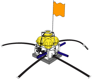
system. A diagram of the instrument configuration is shown in in the
figure on the right.
Data Logger
Each instrument is outfitted with a state-of-the-art,
8 channel, 24-bit data logger. Logging electronics reside in a 7075-T6
aluminum tube which is anodized and painted to resist corrosion by seawater
and terminated
by two end-caps
sealed with O-rings. One end cap has ports to communicate
with the computer and to purge damp air from the instrument. The other end
cap has high-pressure, underwater
connectors for linking the sensors to the logger inputs. The entire
system is capable
of resisting water pressure to depths of 6000 m.
The noise floor for the
analog-to-digital converter is 10-13V2/Hz at 0.01 Hz
to Nyquist. Maximum sampling rates are 1,000 Hz on 4 channels. Power
consumption for 4 channels at 32 Hz sampling is 450 mW. One set of primary lithium
batteries will power the logger for up to 2 months (we've achieved similar endurance using NiMH). Since all the seafloor
instruments are autonomous, accurate
timing
must
be accomplished
by on-board
quartz clocks. The data logger is timed by a custom low-power oscillator
built for SIO with a timing accuracy of about 4 x 10⁻⁸. Phase
locked loops provide all the frequencies required by the system, such as
the 40 kHz
CPU
clock, the 2 kHz for the E-field chopper amplifier, the ADC clock, sample
interrupts, and the software real time clock. The on-board clocks are started
using a GPS time standard, with initial timing accurate to 1-10 microseconds.
After recovery, clocks are again checked against the GPS standard to estimate
drift or error. Drift rates are typically 4 ms per day or so.
Data are stored
on a Flash-ROM drive, capable of recording for up to 2 months. Programming
of the logger for deployments is done through a serial port connection
and recorded data is retrieved via an ethernet interface or by removing the flash card. An onboard electronic
compass and tilt meter record the instruments orientation on the seafloor.
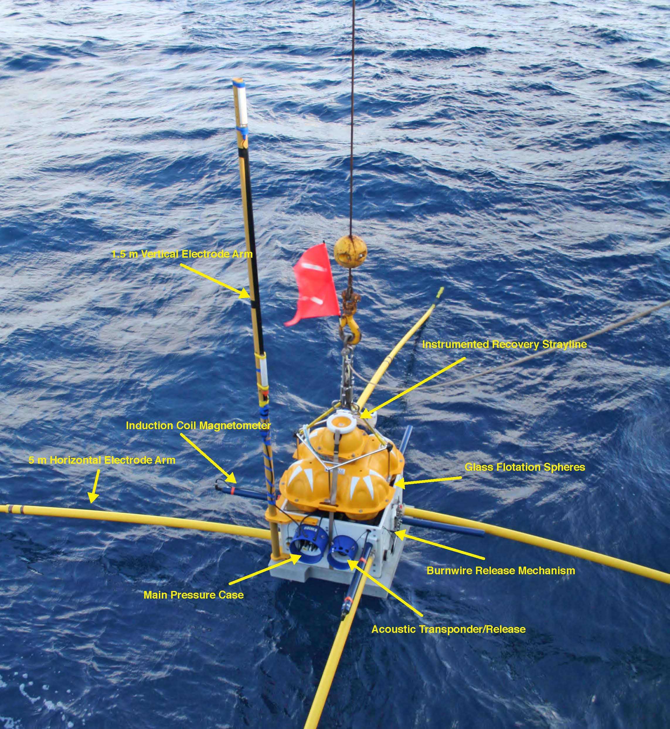
Sensors and Amplifiers
A system of low noise and low impedance silver-silver chloride
electrodes and an AC-coupled electric field amplifier [Webb et al., 1985] measures
the horizontal electric field at the end of 10 m long dipoles. Electric field noise
on the electrode and amplifier system using a 10 m antenna is about 10-10V/m/sqrt(Hz)
at 1 Hz. Horizontal magnetic
fields are measured using sensitive and low
power induction coil magnetometers designed at
Scripps Institution of Oceanography. This configuration makes the instrument
capable of measuring both electric and magnetic fields in the .01 to
10,000 s period range, although the attenuation of the natural source MT
fields
through the ocean limits the shortest periods to about .1-10 s, depending
on the depth of
water.
Frame and Flotation
The logger pressure case is supported in a polyethylene framework
which protects the instrument from damage during handling and supports a pack of four
glass flotation spheres, the acoustic release package, and sensors. Stability A
150 kg concrete anchor stabilizes the instrument
on the seafloor. Early test deployments utilized lead weights for anchors
and often suffered
from motion of the instrument frame seriously corrupting the magnetometer data.
Acoustic Release and Navigation
An independent acoustic unit is used to track the instrument
through the water column during deployment and recovery, and also for releasing
the instrument from the anchor. When the acoustic unit receives a "release"
command form the ship, it sends a current from the 18 V internal batteries
to a short stainless steel burnwire connected to a mechanical release device
securing the concrete anchor to the instrument frame. Within about 4 minutes
this positive voltage
causes the steel wire to electrolyze away, releasing the anchor from
the instrument and allowing the positively buoyant package to float to the
surface
for recovery. Acoustic surveying of the instrument using
this system can determine the seafloor location to within a few meters. Strayline Buoy
A stray-line buoy containing
an LED strobe light, GPS receiver, and radio modem ensure instrument recoveries
can be performed at night and in limited visibility conditions during daylight.
In addition to allowing the instrument to be located on the sea surface, the
strayline buoy is integral to easy recovery of the instrument in all weather
conditions by being attached to the instrument frame via a
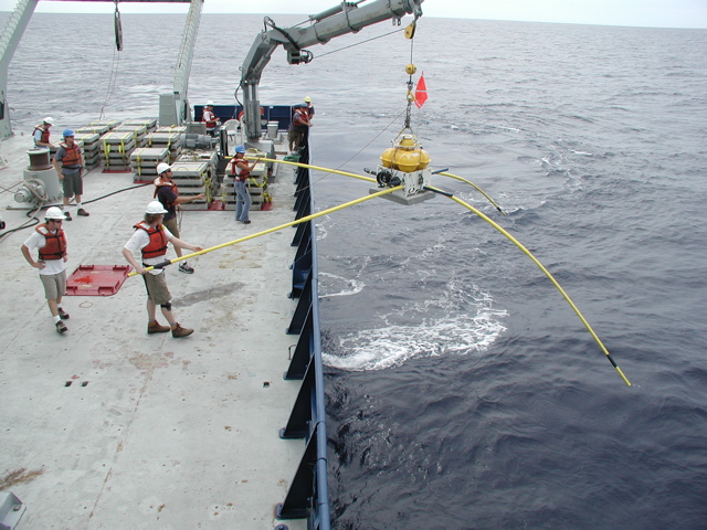
10 m polypropelene rope. During an instrument recovery, the ship will drive up to
about 5-20 m away from the floating instrument and the strayline rope is hooked
using a SIO designed floating plastic grapnel. The strayline is then detached,
and
the instrument hooked to a small ship's crane, which lifts the instrument aboard.
|