GPS Based Instrument Recovery Stray Line Buoys
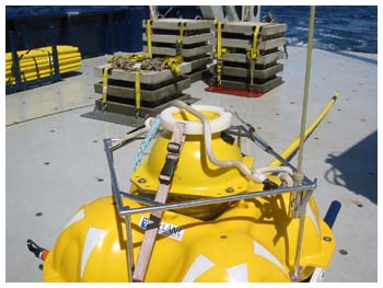
We have developed a new generation of stray line instrument
recovery buoys which contain a GPS receiver and a radio
modem that allows the buoy to report its position when it
reaches the surface. Combined with its bright white led
strobe this simplifies instrument location and recovery
in most lighting and weather conditions.
System Description
Buoy
The stray line buoy is based on a 10 inch Benthos glass
instrument housing with a depth rating of 6700 mrs.
Contained within this are a GPS receiver, radio modem,
PIC microprocessor, LED strobe light, solar panels,
batteries and the supporting electronics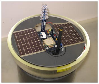
Upon rising to the surface the buoy assumes its normal
non-inverted position and a mercury tilt switch powers up
the system. A delay circuit is included to prevent the system
turning off again on rough seas.The microprocessor then
initializes both radios, transmits the buoy identification
code plus an "ON SURFACE" message and attempts
to obtain a valid GPS location. At periodic intervals (user
configurable- typically 30 seconds) the buoy transmits its
identification and location or, if a valid GPS location
is not available, the message "WAITING FOR GPS".
After a defined amount of time (user defined-typically
3 hours) it may be assumed that the instrument has not
been recovered. At this time the buoy enters a power saving
mode where it goes to 'sleep' , waking every hour on the
hour and transmitting its location for a few minutes before
going to 'sleep' again. The buoy contains solar panels
that are intended to provide enough power to keep the
buoy running in this low power mode indefinitely.
Ship Board Repeater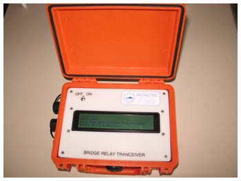
In its simplest configuration an antenna and radio modem
connected to a computer or terminal on the ship can be used
to receive the data from buoy.
We have however developed a repeater that can be used
to retransmit location data from the buoy to mobile receivers
anywhere in the ship. This consists of a radio modem, a
GPS receiver, and a microprocessor. It may be powered by
internal batteries, or low voltage power run from a suitable
location on the ship. It is typically mounted close to its
receiving antenna high up on the ship (above the bridge
house) where it has a good 'view' of the surrounding ocean.
This repeater receives GPS identification and location
data from the buoy. Then using the GPS receiver inside
the repeater it calculates the bearing and distance if
the buoy and retransmits this information along with the
original buoy and local GPS data.
Ship Board Data Receivers and Hand Held Terminal
Two types of receivers are used with this system.
Radio Modem
Using a radio modem interfaced to a laptop, it is possible
to view and log the recovery data being relayed from
the buoy. With the addition of some custom software
a graphical representation of the ship's location
and the relative position of the instrument is also
possible. This requires no additional data as the
repeater is re-transmitting the GPS location of the
ship, the location of the buoy and its bearing and
distance.
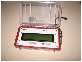
Handheld terminal
The handheld terminal contains a radio modem, lcd display,
microprocessor and batteries. This portable terminal may
be used to display data from the repeater. In addition
it contains configurable audio and visual alerts to warn
of instruments that may have arrived on the surface unexpectedly.
Buoy Specifications |
|
Transmitter frequency
Transmitter power
Time to first GPS fix: hot start
Time to first GPS fix: cold start
Operating temperature
|
918MHz
1 watt max
3 secs
40 secs
-40 deg C - 85 deg C
|
Additional functionality
The electronics are sealed inside the glass sphere and
the process of opening and resealing a sphere can be time
consuming with the possible risk of damage. For this reason,one
of the design requirements is that the software running
the embedded controller can be upgraded without opening
the sphere. Using a radio modem and special PC based software,
the microprocessor in the buoy can be completely reprogrammed
without opening the glass sphere using the radio modem.
In addition, there are a number of text commands that may
be sent via the radio modem to set user configurable parameters
in the buoy.
These include setting
- 4 character buoy ID that is transmitted with each message
- transmitter power level
- number of times each message is retransmitted
- minutes to run before power save mode is entered
- wake up times when in low power mode
- minutes to transmit before reentering sleep when on
low power mode
- strobe on/off light level
- strobe flash rate, duration and pattern
- control over the contents and format of the output messages
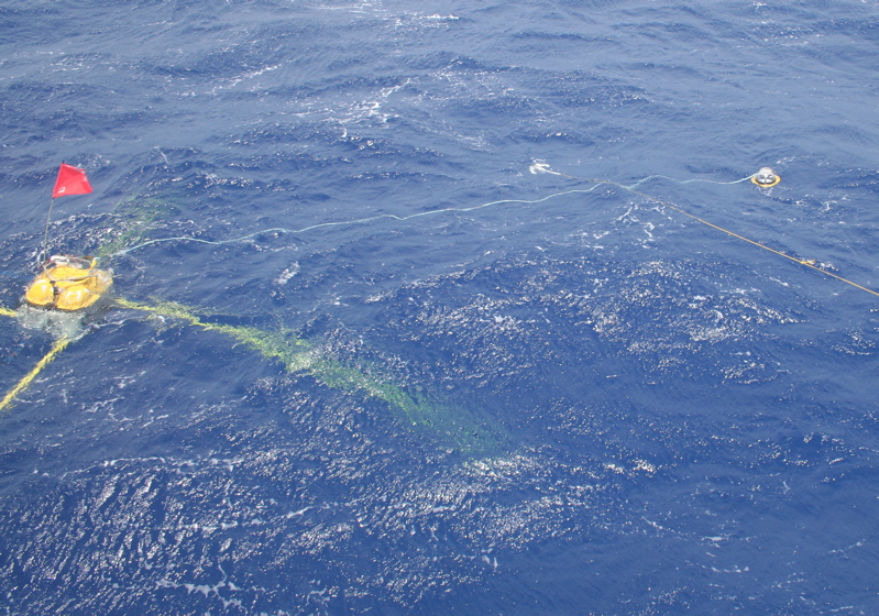
Rapid Instrument Recover with Stray Line Buoys
This image shows a strayline buoy (far
right) attached by a 30 foot tether (blue nylon rope)
to a seafloor electromagnetic receiver (far left). A
floating grapnel hook attached to the yellow rope was
thrown from the ship over the strayline. The buoy is
then pulled aboard the ship, the blue tether is secured
to the ship's crane and the EM receiver is lifted
onto the ship's deck.
|