Instruments | EM Receiver | Data Format
The following delineates how information and data are stored on both the MkII
and MkIII data loggers. Prior to 2001 some or all data files are in 16 bit
format; all data files after this are 24 bit. The data structure is designed
for maximum flexibility, but many features are not currently used, specifically
gain ranging and compression.
All data are stored in 512-byte blocks. The diagram below shows the basic
architecture of the unformatted disk drive. Blocks 0-1 are not written by the
instrument software and are reserved for "system overhead" as needed
(yellow). Block 2 contains the "Disk Header" (orange) which includes
information regarding the location of a "Directory" (blue) that tabulates
the location of the data on the disk (green). In practice, the directory is
on the order of a hundred blocks in size. 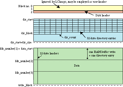
The structure of the Disk Header and Directory was designed with a number
of features which are not being used at this time. Several terms need to
be defined in order to understand the data structure. "Normal Data" refers
to data acquired at the interrupt rate or at some small fraction thereof. "Slow
Data" refers to data acquired at a very low sample rate (once or twice
per hour) simultaneously with Normal Data acquisition. For example, data
from the onboard compass tiltmeter are written as Slow Data. "Log
Data" refers
to additional information to be stored other than normal data and Slow Data.
The term "Time Tag" will be used below to describe time logged
as follows:
| Byte no. |
Name |
Function |
| 1-2 |
msecs |
milliseconds |
| 3 |
secs |
second number |
| 4 |
min |
minute number |
| 5 |
hour |
hour number |
| 6 |
day |
day number |
| 7 |
month |
month number |
| 8 |
year |
year number |
The 16-bit versions of the code are NOT Y2K compliant, because they cannot
be set to year '00'. To solve this, 1972 is substituted for 2000, as it is
also a leap year and pre-dates the existence of the loggers.
DISK HEADER STRUCTURE:
The disk header in block number 2 has the following structure:
| Byte no's. |
Name |
Function |
| 1-4 |
write_block |
Block no. for next normal data write |
| 5-6 |
write_byte |
Byte number in write_block for next data write (always 00) |
| 7-12 |
read_block, read_byte |
not used |
| 13-16 |
dir-start |
Block no. where directory starts |
| 17-20 |
dir_size |
No. of blocks in directory allocation |
| 21-24 |
dir_block |
Block no. for next directory entry |
| 25-28 |
dir_count |
No. of next directory entriy in current block |
| 29-44 |
|
Slow data information (not used) |
| 45-60 |
|
Log data information (not used) |
| 61-64 |
data_start |
Block number at which normal data starts |
| 65-66 |
disk_number |
Number of disk in 2-drive instrument (usually 00) |
| 67-76 |
soft_version |
Software version number used to acquire data |
| 77-156 |
description |
Experiment description as entered by user at startup time |
| 157-158 |
sample_rate |
Sample rate of normal data |
| 159-160 |
start_chan |
Channel number of first normal data on disk (usually 00) |
| 161-162 |
num_channel |
Number of channels being recorded |
| 163-168 |
|
Slow data information (not used) |
| 169-170 |
data_type |
0=16-bit; 1=compressed 16-bit; 2=24-bit; 3=comp. 24-bit |
| 171-172 |
disk_size |
Capacity of disk drive installed in instrument |
| 173-174 |
ram_disk_size |
Capacity of PCMCIA RAM data buffer |
| 175-512 |
|
not used |
DIRECTORY ENTRY STRUCTURE:
Each directory entry corresponds to one "record" or RAM buffer
full of data written to disk. The structure of each directory entry is:
| Byte no.'s |
Name |
Function |
| 1-8 |
start_time |
Time of first data sample in record (see time tag structure above) |
| 9-12 |
blk_number |
Block number for location of first sample |
| 13-16 |
rec_length |
not used |
| 17-18 |
sample_rate |
Sample rate for normal data |
| 19-20 |
num_blocks |
Number of blocks in this record |
| 21 |
block_flag |
8-bit status code: see below |
| 22 |
mux_chan |
8-bit code: see below |
| 23-32 |
spare |
not used |
STATUS CODES:
Bits in block_flag and mux_chan are as follows:
| Bit no. |
Function |
| 7 (MSB) |
- 0 = data in this block are for one channel only
- mux_chan 4 LSBs = channel number for this block
- mux_chan 4 MSBs = pre-amp gain code (0000 if VGP not used)
- 1 = data are multiplexed within the block
- mux_chan = number of channels multiplexed in block
|
| 6 |
- 0 = block is a data block
- 1 = block is a status block
|
| 5 |
- 0 = normal data
- 1 = 24-bit data
|
| 4 |
- 0 = normal data
- 1 = compressed data
|
| 3 |
- 0 = normal data
- 1 = data with variable gain preamp (VGP) and automatic gain ranging
(AGC)
|
| 2 |
- 0 = normal data
- 1 = a time tare has occurred
|
| 1 |
not used |
| 0 (LSB) |
- not used (=1)
|
DATA
The Marine EM Lab has only collected 16 and 24 bit uncompressed data, but
in the OBS Lab has collected other types of data, which are mentioned here
for completeness:
A) 16-bit, uncompressed data.
B) 16-bit data with variable gain preamp (VGP) and automatic gain ranging
(AGC).
C) 'WHALES' data, a one-off experiment using 16-bit, compressed, windowed,
4kHz sampling.
D) 24-bit, uncompressed data.
E) 24-bit, compressed data. (This feature is not yet implemented)
The basic data format is a 12-byte header at the beginning of each 512-byte
block, followed by 2 bytes ('compression bytes') indicating the type of data
and the number of samples in the following bytes. For uncompressed data,
the rest of the block is simple data. For compressed data, there may be repeated
groups of 2 compression bytes followed by data.
For uncompressed, non-VGP/AGC 16-bit data (type A), each disk block has
14 bytes of header plus compression bytes, followed by 498 bytes of data
stored in 2's complement, 2-byte integers (byte ordering is correct of Macintosh
and Unix machines; bytes must be swapped for Wintel machines). That is, a
total of 249 2-byte data.
For uncompressed 24-bit data, each disk block has 14-bytes of header and
compression bytes followed by 498 bytes of data stored in 2's complement,
2-byte integers (byte ordering is correct of Macintosh and Unix machines;
bytes must be swapped for Wintel machines). That is, a total of 166 3-byte
data.
For compressed, and/or VGP/AGC data, the 12-byte block header is followed
by information about compression and gain ranging in byte 13, followed by
the number of data in byte 14. If the block is not filled, then the data
chunk is followed by 2 more 'compression' bytes with new preamp/gain ranging
codes and number of samples, followed by that number of samples again, etc.
The data chunk starts with a single uncompressed datum followed by 8-bit
or 16-bit first differences.
Data are block multiplexed. The status codes in the block header document
the channel number for each block.
BLOCK HEADERS
The header structure is as follows:
| Byte no.'s |
Name |
Function |
| 1-8 |
start time |
Time of first data sample in block (see time tag format) |
| 9 |
block_flag |
8-bit status code (see status codes) |
| 10 |
mux_chan |
multiplex code (see status codes) |
| 11-12 |
num_samples |
Binary number describing number of samples in block (not set) |
| 13 |
?? |
variable gain preamp and gain ranging codes (see below) |
| 14 |
?? |
number of samples in next chunk of data |
Byte 13 in block headers for gain ranged data:
| bit no. |
Function |
| 7 (MSB) |
- 0 = uncompressed data
- 1 = compressed data
|
| 6 |
- 0 = 8-bit differences stored for compressed data (16 or 24 bit)
- 1 = 16-bit differences stored for compressed data (24 bit only)
|
| 5 |
- 0 = 16-bit data
- 1 = 24 bit data
|
| 4 |
unused |
| 0-3 |
gain range code |
|
